
Wiring#
This guide walks through the electrical wiring of Micipsa, connecting the power distribution, compute, and sensor components onto the assembled chassis.
Note
This guide assumes all parts listed in the 3D Printing documentation have already been printed and assembled.
Extender Disassembly#
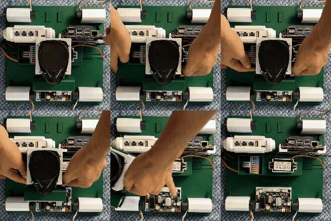
- Slide out the extender bracket
Fuse Wiring#
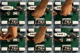
- Connect the Fuse Positive to the input red slot of the wire multiplicator
- Connect the battery Negative to the input blue slot of the wire multiplicator
Jetson Wiring#
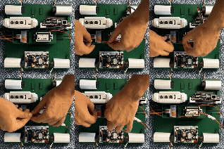
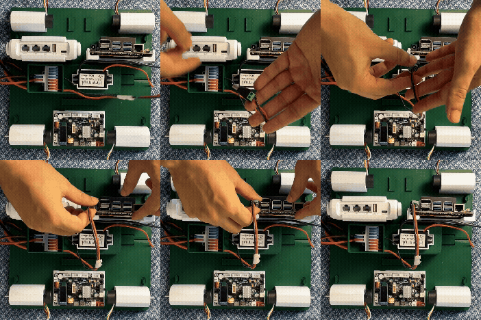
- Connect the Jetson Positive to the output red slot of the wire multiplicator
- Connect the Jetson Negative to the output blue slot of the wire multiplicator
Voltage Converter Wiring#
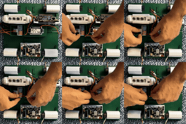
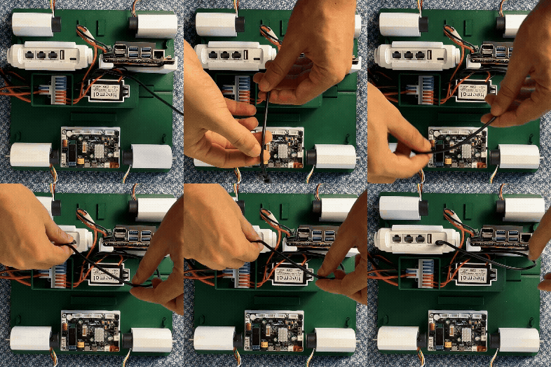
- Connect the Voltage Converter Positive to the output red slot of the wire multiplicator
- Connect the Voltage Converter Negative to the output blue slot of the wire multiplicator
- Connect the Voltage Converter USB cable to the router alimentation USB slot.
MCU Wiring#
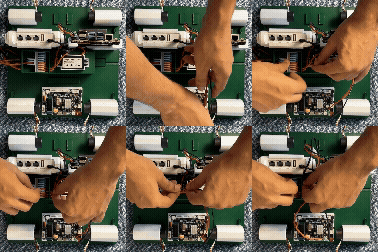
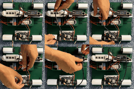
- Connect the supply wires to the MCU red supply Slot
- Connect the MCU supply wires Positive to the output red slot of the wire multiplicator
- Connect the MCU supply wires Negative to the output blue slot of the wire multiplicator
- Connect the MCU USB cable to the Jetson USB Slot.
Router Wiring#
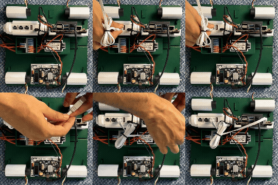
- Connect the ethernet cable to the router and to the jetson ethernet slots
Motors Wiring#
Note
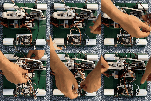
Front Left Motor is on the bottom right of the image.
- Connect the front left motor to the M1 Slot on the MCU Board
- Connect the front right motor to the M3 Slot on the MCU Board
- Connect the back left motor to the M4 Slot on the MCU Board
- Connect the back right motor to the M2 Slot on the MCU Board
Extender Reassembly#
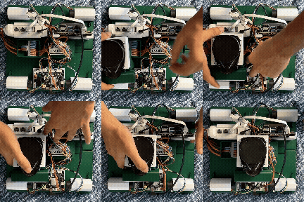
- Reposition the extender in its dedicated slot and position.
Lidar Wiring#
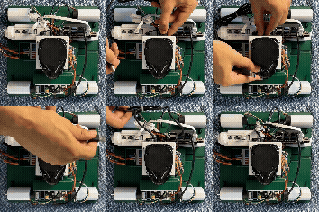
- Connect the Lidar USB cable to its adapter and to the jetson USB slot
Camera Wiring#
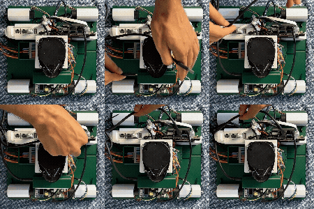
- Connect the Camera USB cable to its slot and to the jetson USB slot
Battery Wiring#
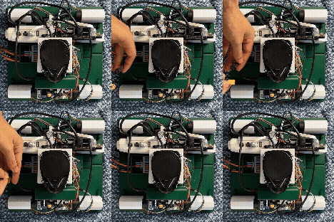
- Connect the Battery cable to the Fuse cable connector.
Final Checks#
Once the Battery Wiring is complete, the MCU, Jetson and router should power on and the Lidar should start spinning, confirming that the wiring has been done correctly.