



Assembly#
This guide walks through the physical assembly of Micipsa, from individual component sub-assemblies through to their integration onto the chassis.

Note
This guide assumes all parts listed in the 3D Printing documentation have already been printed and post-processed. Refer to that page for the complete list of printed components.
Important
If a part does not sit tightly in its dovetail slot on the chassis, the dovetail draft angle is likely too small.
If you haven't already, refer to the pre-printing section of the 3D Printing documentation to adjust it.
If the chassis has already been printed, avoid reprinting it (and wasting filament and time) by instead updating the hardware support's dovetail dimensions to reduce the slot size.
Phase 1: Component Assembly#
Motor Assembly#
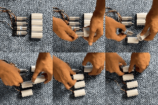
- Slide into place until you feel it reaches the end stop.
- If needed, screw the motors into their support.
Router Assembly#
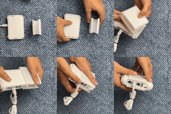
- Slide into place until it sits well in the middle of the support
Jetson Assembly#
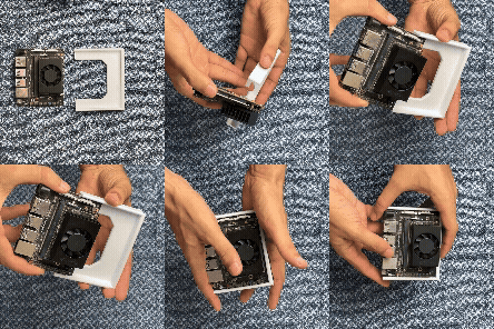
- Slide into place until you feel it reaches the end stop.
MCU Assembly#
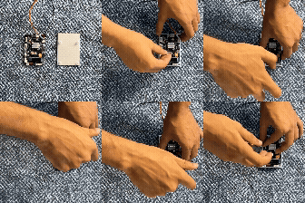
- Put on the support and screw it in the dedicated holes.
Battery Assembly#
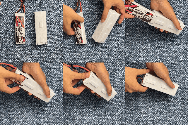
- Slide into place until you feel it reaches the end stop.
Camera Assembly#
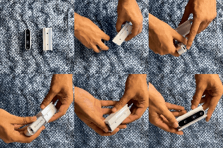
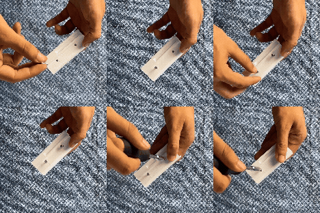
- Slide into place until you feel it reaches the end stop.
- Use screw to attach it tightly.
Lidar Assembly#
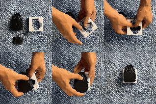
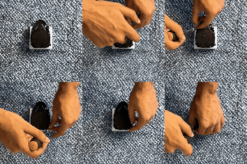
- First slide the lidar hub into the dedicated place until it snaps in place.
- Place the lidar in the top and in the correct orientation as in the image.
- Use screw to attach it tightly on the support.
Extender Assembly#
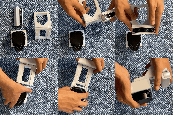
- For both component slide into place until you feel it reaches the end stop.
Voltage Converter Assembly#

- Push it into its support until it snaps in place.
Wire Multiplicator Assembly#
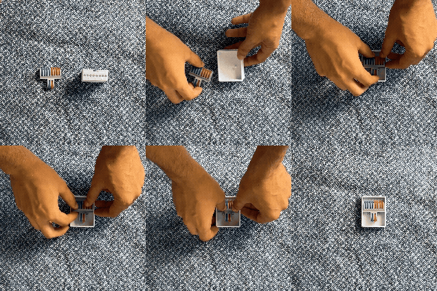
- Push it into its support until it snaps in place with the help of the two guiding cylinders.
Phase 2: Chassis Integration#
Motors → Chassis#
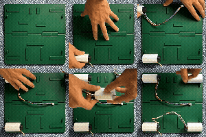
- Align each motor bracket with its dovetail slot on the chassis.
- Slide into place until you feel it reaches the end stop.
- Repeat for all four motors
Router → Chassis#
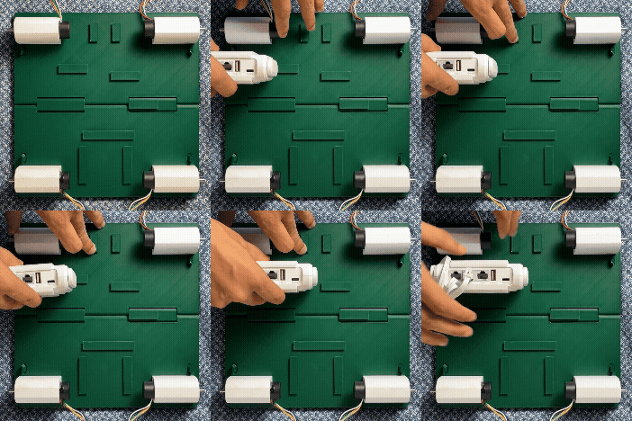
- Align the router bracket with its dovetail slot on the chassis.
- Slide into place until you feel it reaches the end stop.
Jetson → Chassis#
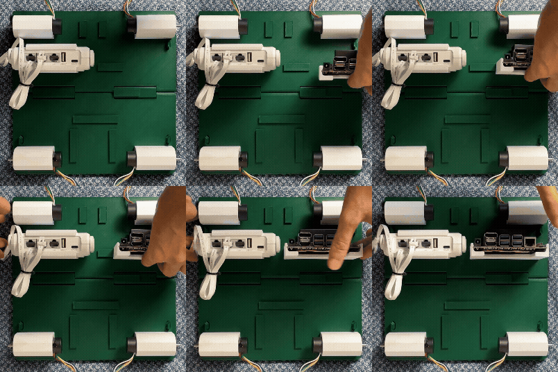
- Align the jetson bracket with its dovetail slot on the chassis.
- Slide into place until you feel it reaches the end stop.
MCU → Chassis#
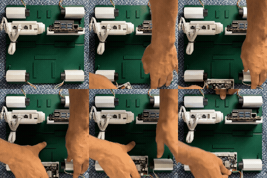
- Align the MCU bracket with its dovetail slot on the chassis.
- Slide into place until you feel it reaches the end stop.
Battery → Chassis#
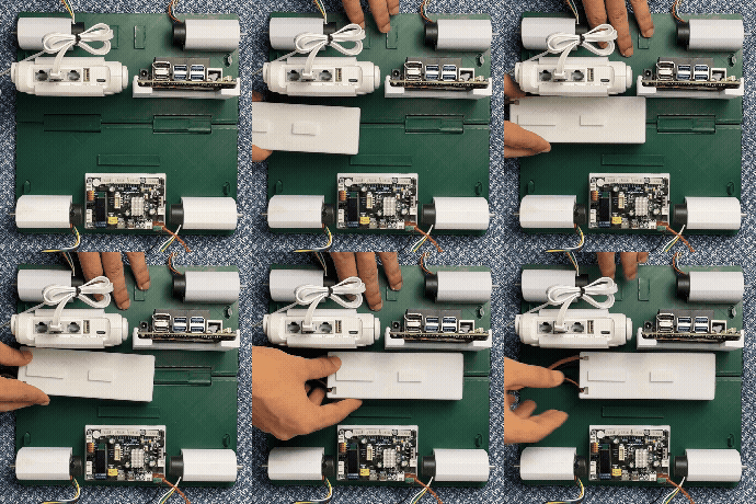
- Align the battery bracket with its dovetail slot on the chassis.
- Slide into place until you feel it reaches the end stop.
Voltage Converter → Chassis#
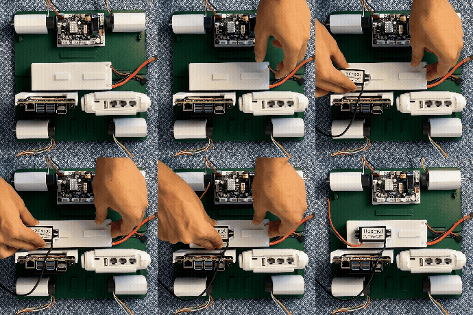
- Align the voltage converter bracket with its dovetail slot on the battery bracket.
- Slide into place until you feel it reaches the end stop.
Wire Multiplicator → Chassis#
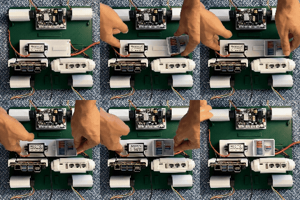
- Align the wire multiplicator bracket with its dovetail slot on the battery bracket.
- Slide into place until you feel it reaches the end stop.
Extender → Chassis#
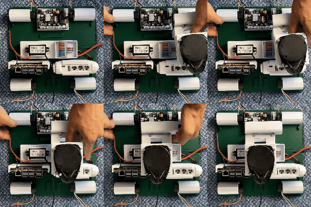
- Align the extender bracket with its dovetail slot on the chassis.
- Slide into place until you feel it reaches the end stop.
Final Checks#
Important
After assembly, the robot should be shaken firmly (above a safe and soft surface) to confirm that all components are seated securely and can withstand small to moderate vibration or minor impacts without sliding out of their mounting slots.