


3D Printing Guide#
This guide documents every 3D-printed part used in the MICIPSA robot, explaining not only how each component was designed, but also why specific design decisions, modeling approaches, and engineering solutions were chosen.
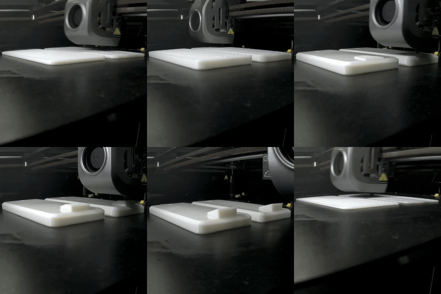
It also provides the printing guidelines and slicer settings used to produce reliable parts along with recommendations for achieving consistent print quality.
3D Modeling Guidelines#
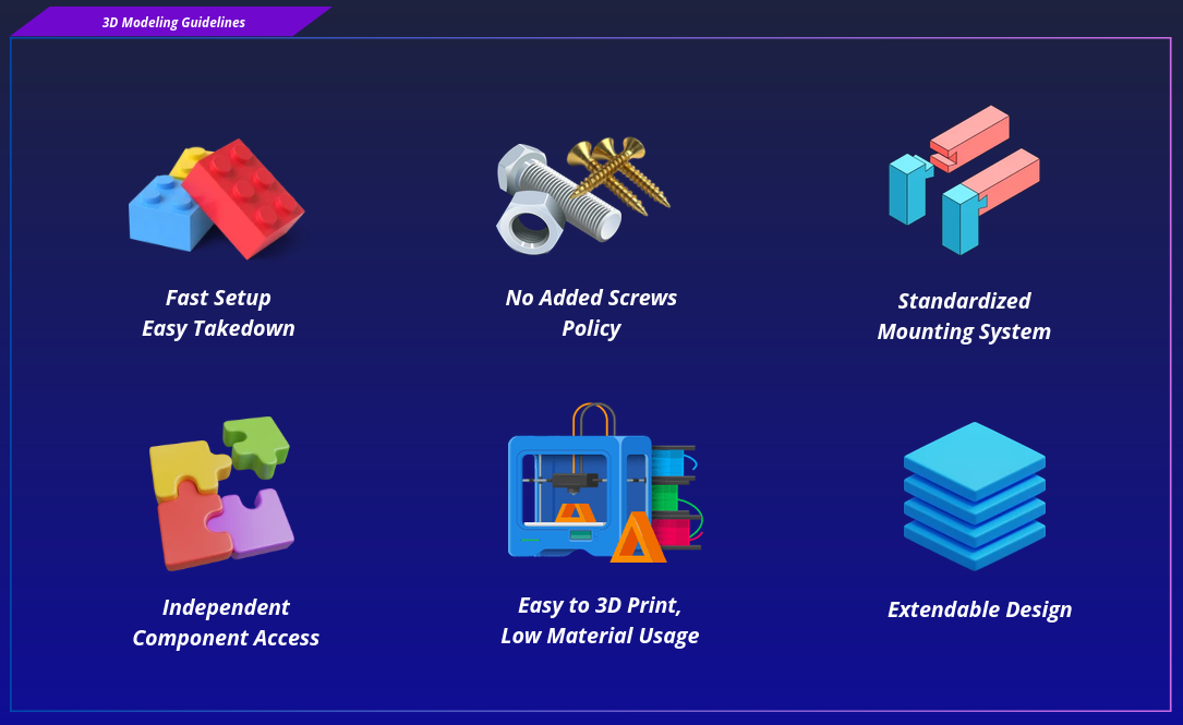
Micipsa's 3D modeling and design followed a set of guidelines aimed at making the robot fast and easy to assemble and disassemble, while keeping the use of screws, bolts, and other fasteners to an absolute minimum.
Fast Setup Easy Takedown#
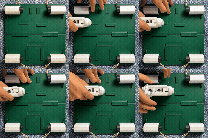
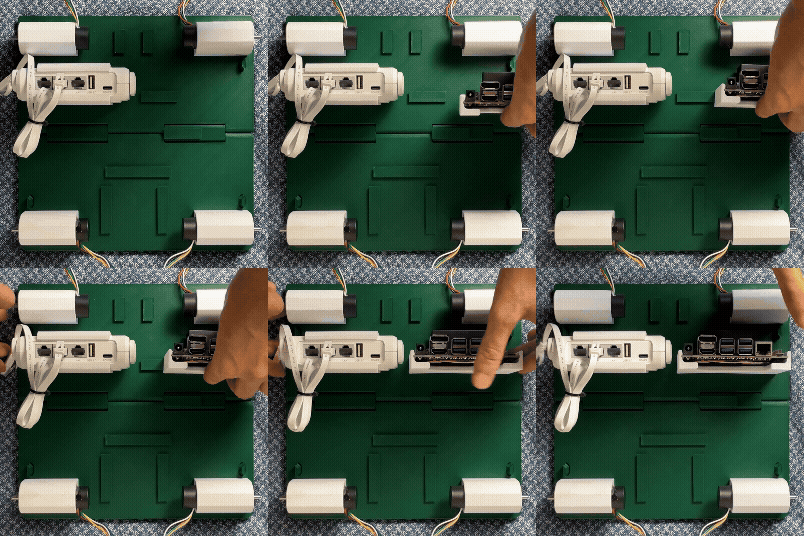
The hardware component is mounted onto its support first, then the support itself slides into place on the chassis and locks by friction alone. Mounting a component is a single motion, slide the support along its rail until it reaches its tightly fitted position and removing it is the same motion in reverse, with no tools involved for the vast majority of parts.
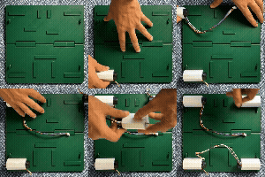
Most components need nothing beyond this tight custom-fitted slide to stay firmly in place. Motors, on the other hand, are secured to their supports using the screws supplied with the motors themselves, as the driving torque and shear forces could eventually loosen a friction-fit connection. This ensures that the motors remain firmly in place once mounted.
This turns what would normally be a multi-step assembly job into something that takes seconds, whether it's the first build, a field repair, or a full teardown for transport.
No Added Screws Policy#
Fasteners are reserved for cases where the mounting system alone may not alone guarantee correct behavior of the hardware such as attaching a motor to its support (torque and shear loads), and mounting components sensitive to vibration or micro-movement such as the IMU, the camera, and the LiDAR.
As a result, the only screws, bolts, and other fasteners used are those supplied with the purchased hardware and comes with it.

Standardized Mounting System#
Every support, regardless of what it holds, uses the same mounting system interface to attach to the chassis. This keeps the design consistent, makes supports interchangeable between mounting points where geometry allows, and means a new support only needs to be designed against one mechanical standard rather than a custom one each time.
Independent Component Access#
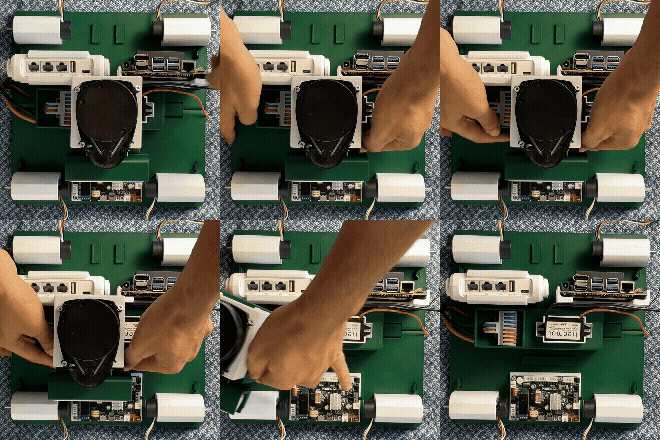
Any single component can be removed from the robot without removing or loosening any other component. The only prerequisite is disconnecting that component's own cables.
There is no specific stacking order to follow, and no component obstructs access to another, except when the wheels are installed at the very end. Even with the wheels in place, components remain easy to disassemble, as the motor supports can simply be slid out in a matter of seconds. Each support can therefore be accessed and removed independently.
Easy 3D Print Low Material Usage#
Every support is modeled from the start with printability in mind. Overhangs are kept within self-supporting angles, chamfers and fillets replace sharp unsupported edges where possible, and geometry is built around the printer's natural strengths so that a part can go from the bed to the robot with minimal print supports or any post-processing. Wall thickness is sized to what the part actually needs to carry keeping each support light on material without giving up strength where it matters.
Extendable Design#
New mounting points can be added directly onto the chassis to support additional hardware, and the robot can even be grown vertically by adding a whole new stage or floor on top of the existing structure.
3D Printing Guidelines#
Important
DO NOT SKIP Robot Pre-Printing Section as it may save you tremendous amount of time.
Robot Pre-Printing#
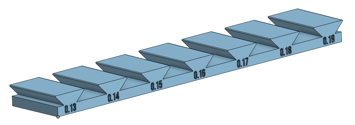
Before printing any robot component, it is strongly recommended to print the Dovetail Joint Assembly Test first.
Micipsa parts are assembled using dovetail joints. While the CAD models are designed with specific clearances, the final fit depends on your printer's dimensional accuracy. Factors such as printer calibration, material, nozzle condition, and even filament brand can all affect the resulting tolerances.
Because of these variations, the same parts may produce:
- A joint that slides together too easily, resulting in a loose connection.
- A joint that is excessively tight or impossible to assemble without excessive force.
The Dovetail Joint Assembly Test allows you to determine the draft angle (default draft angle is 0.16°) for your specific printer before committing to a full robot part.
If necessary, you can adjust the dovetail draft angle in the CAD model based on the test results and then print the final components.
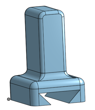
Spending a few minutes printing the test piece can save many hours of print time and a significant amount of filament by avoiding failed parts that must be reprinted due to poor fit.
Robot Printing#
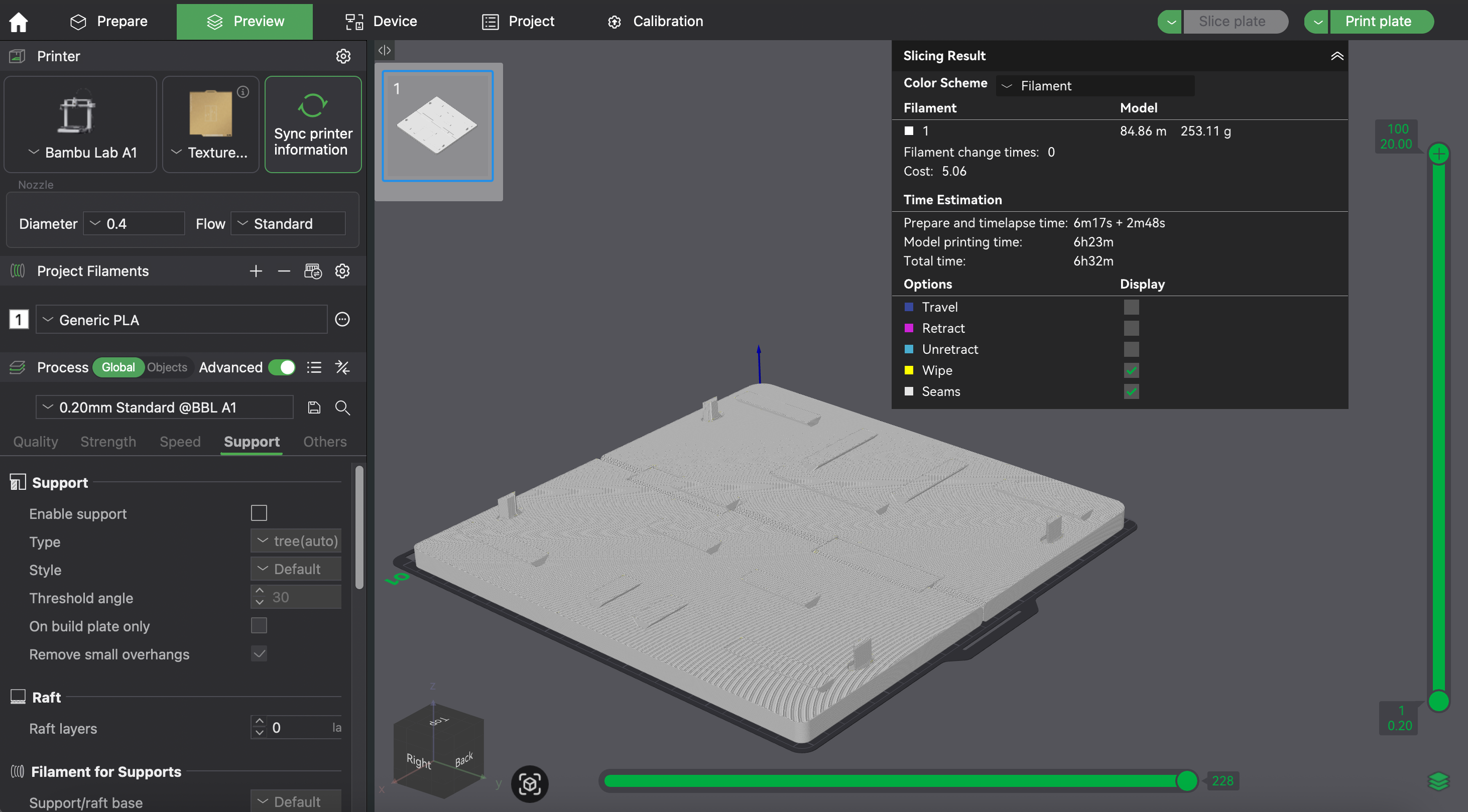
Common Slicer Settings#
| Setting | Value |
|---|---|
| Slicer | Bambu Studio |
| Nozzle | 0.4 mm |
| Material | PLA |
| Layer Height | 0.2 mm |
| Infill | 15% |
| Wall Loops | 2 |
| Bed Temperature | 80 °C |
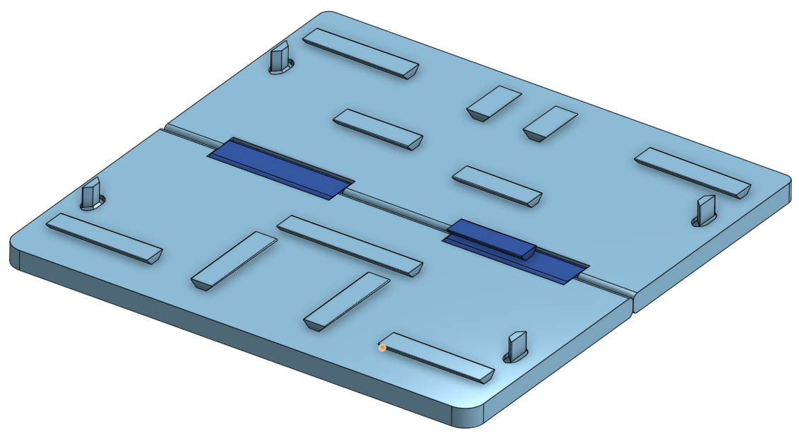
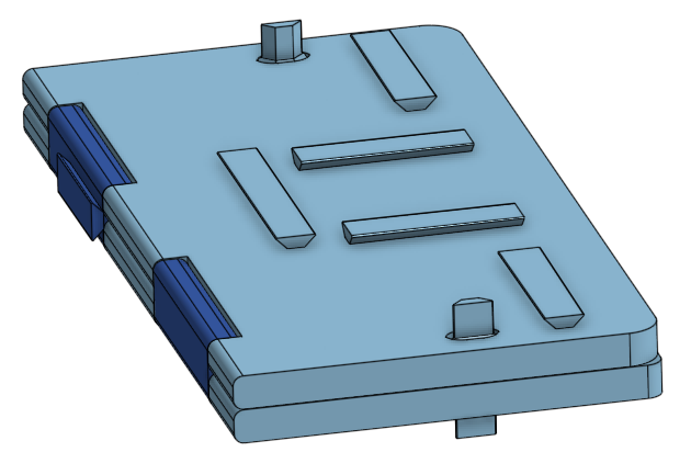
Chassis#
- Common Slicer Settings
- Supports: No
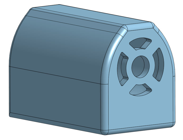
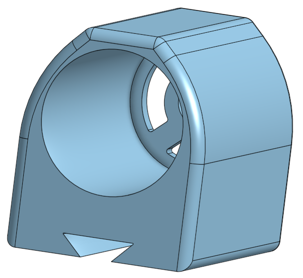
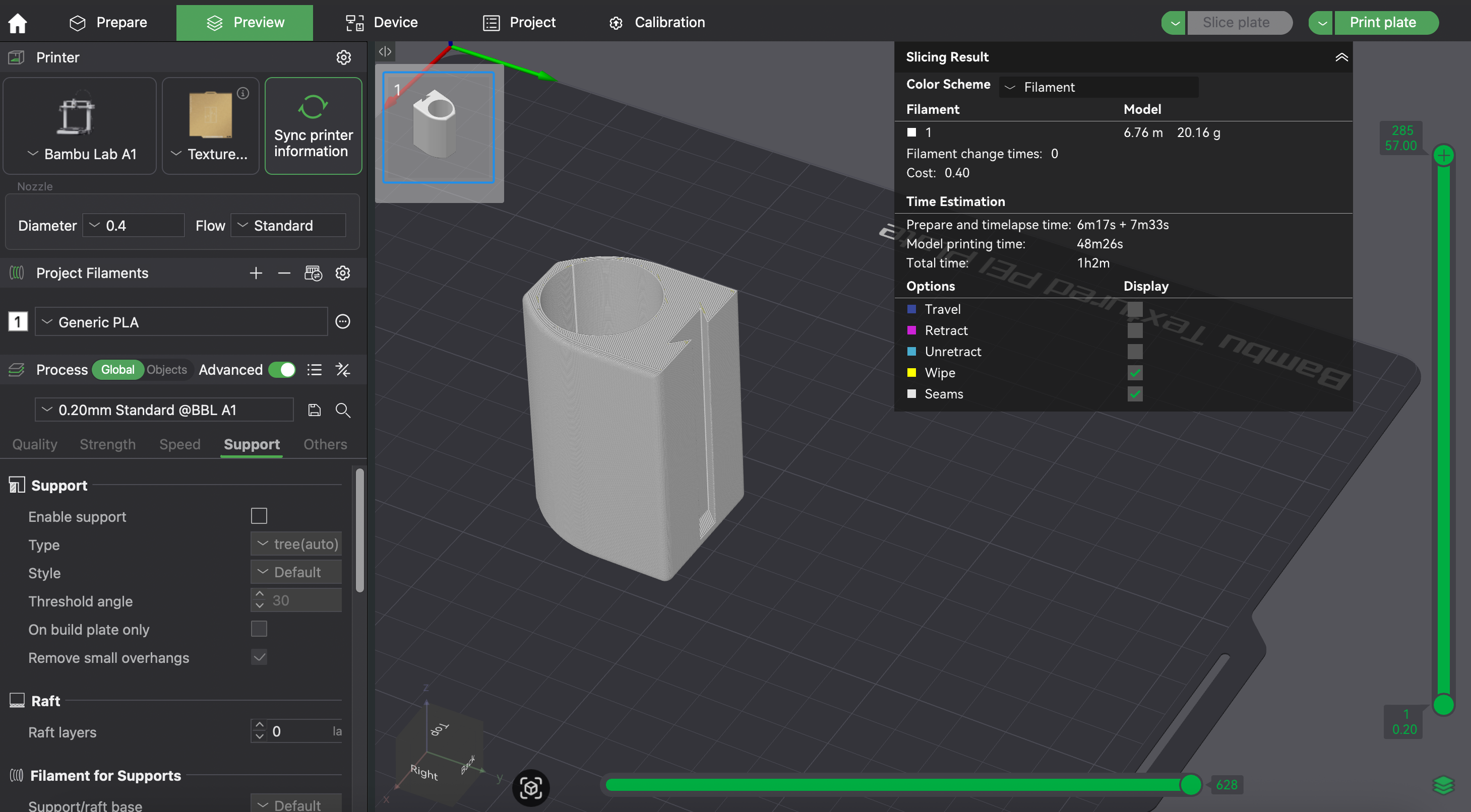
Motor Support#
- Common Slicer Settings
- Supports: No
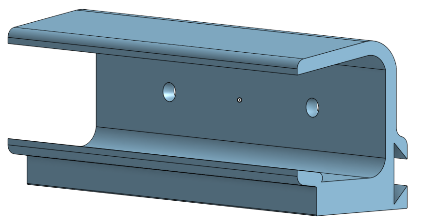
Camera Support#
- Common Slicer Settings
- Supports: No
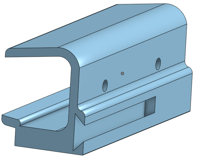
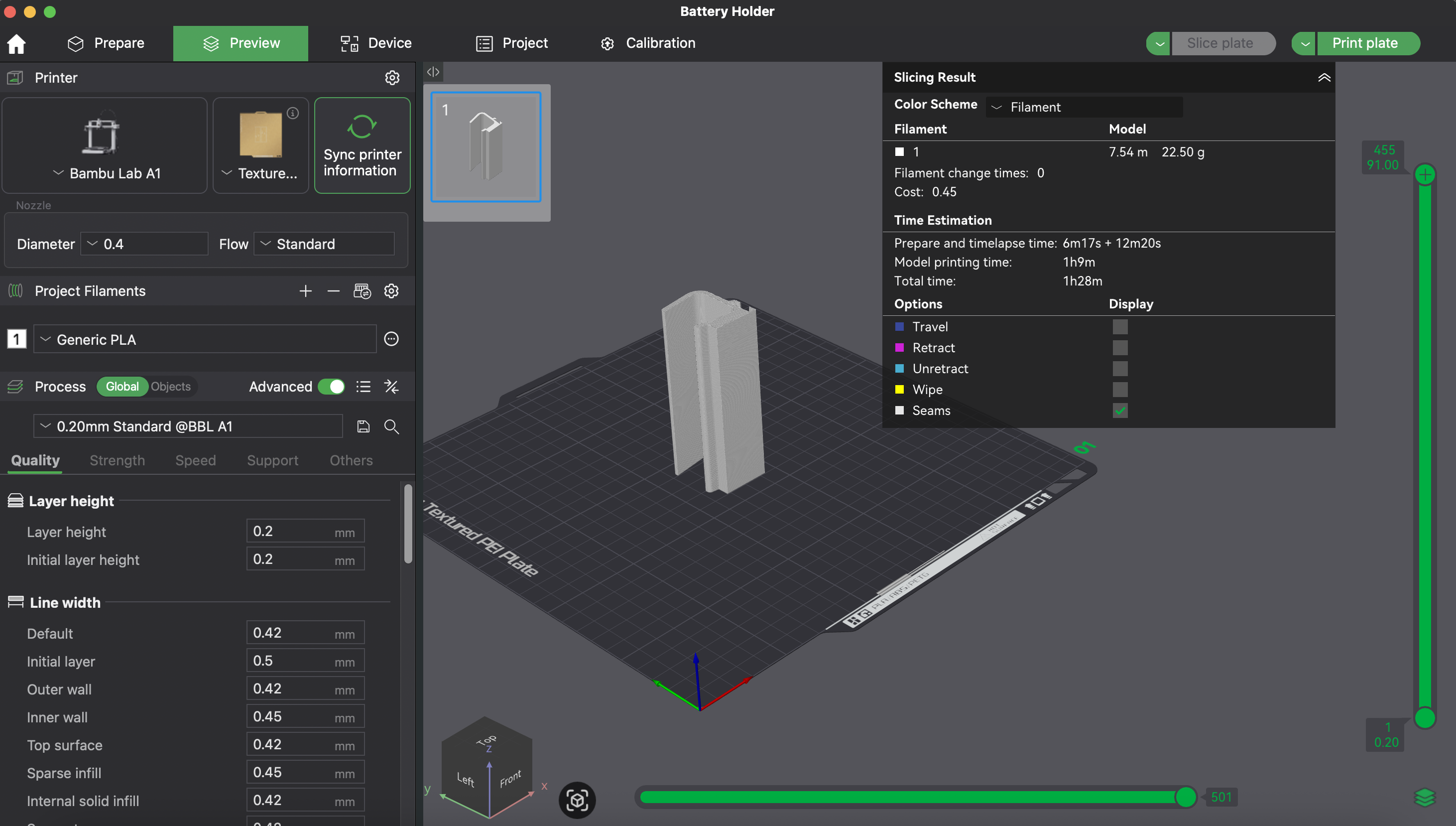
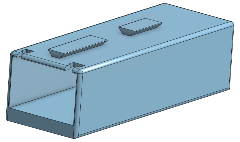
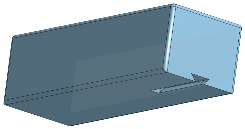
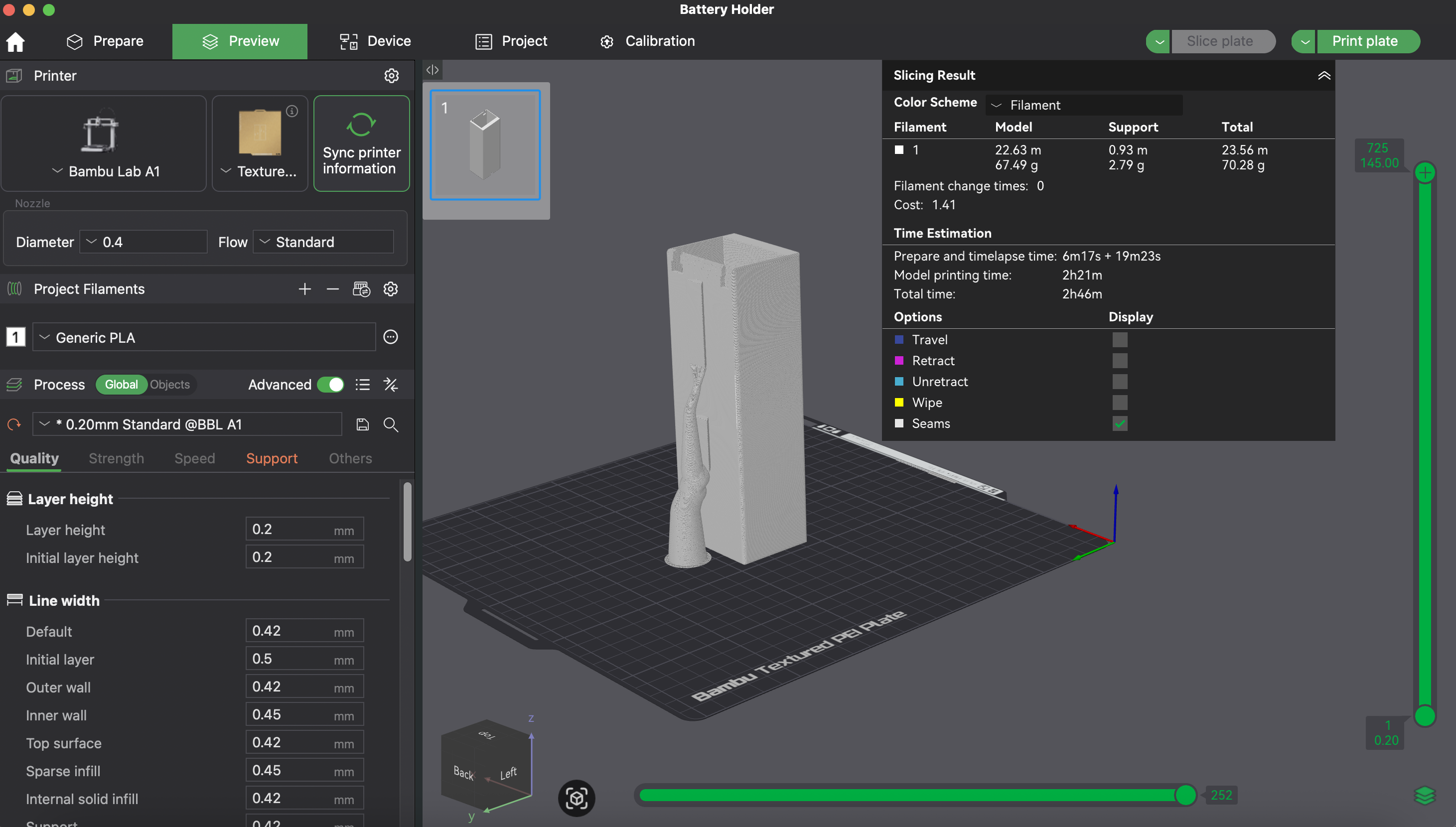
Battery Support#
- Common Slicer Settings
- Supports: Yes
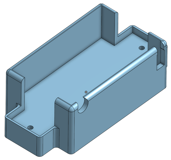
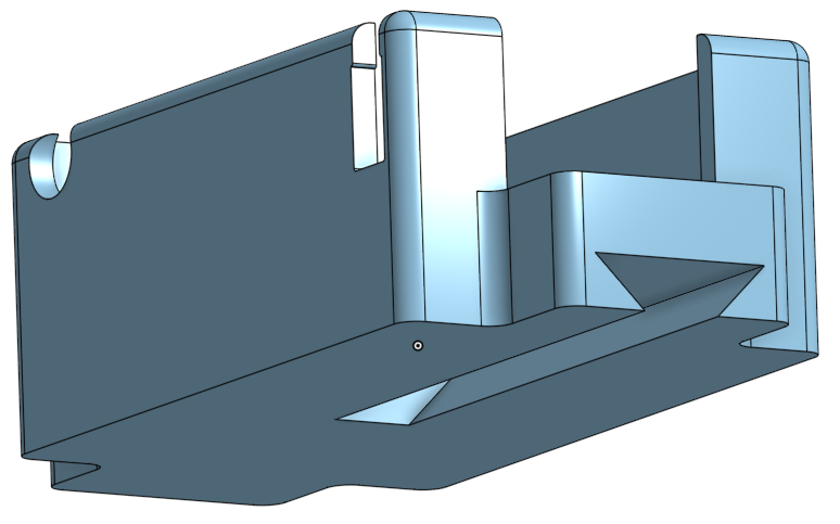
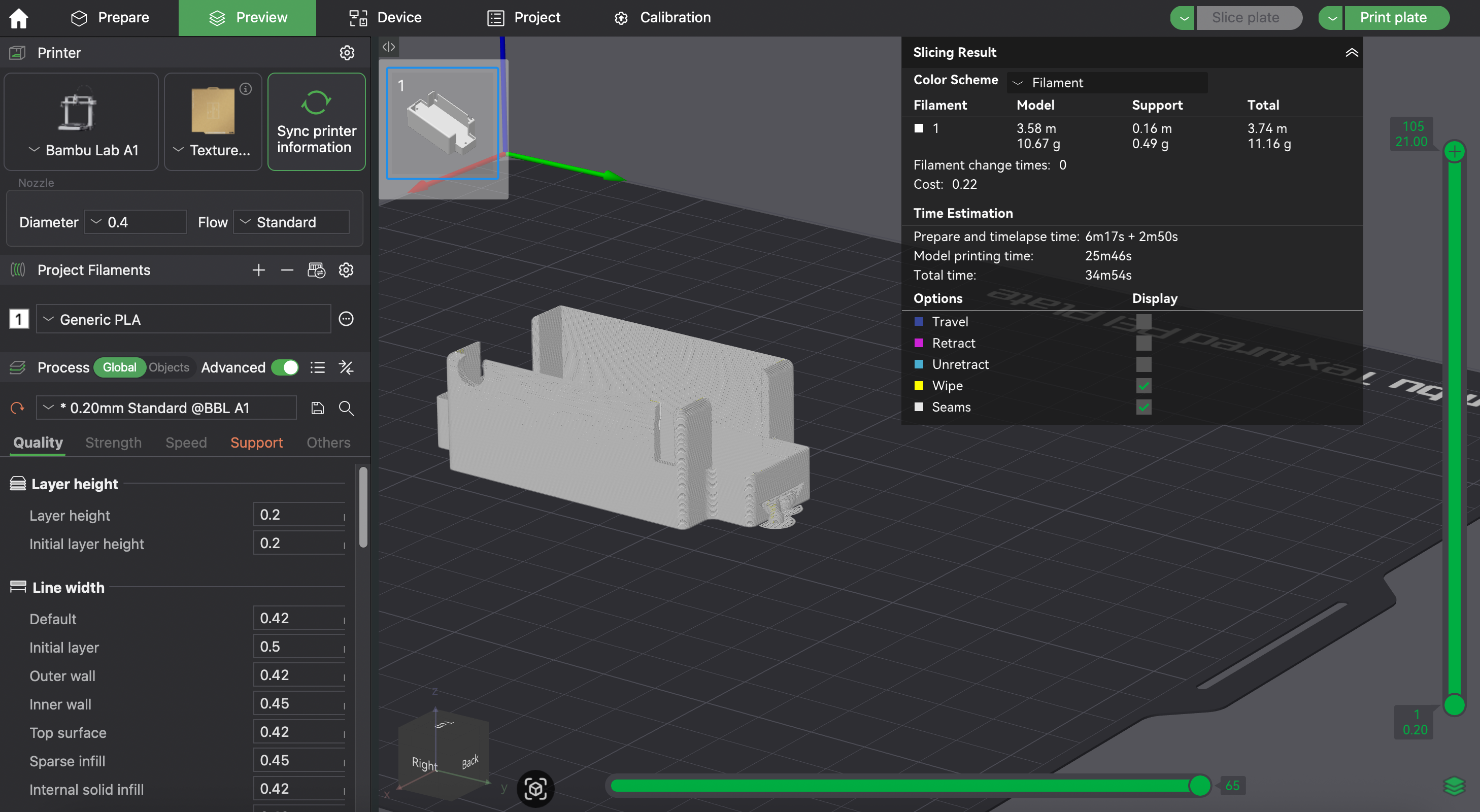
Voltage Converter Support#
- Common Slicer Settings
- Supports: Yes
Wire Multiplicator Support#
- Common Slicer Settings
- Supports: Yes
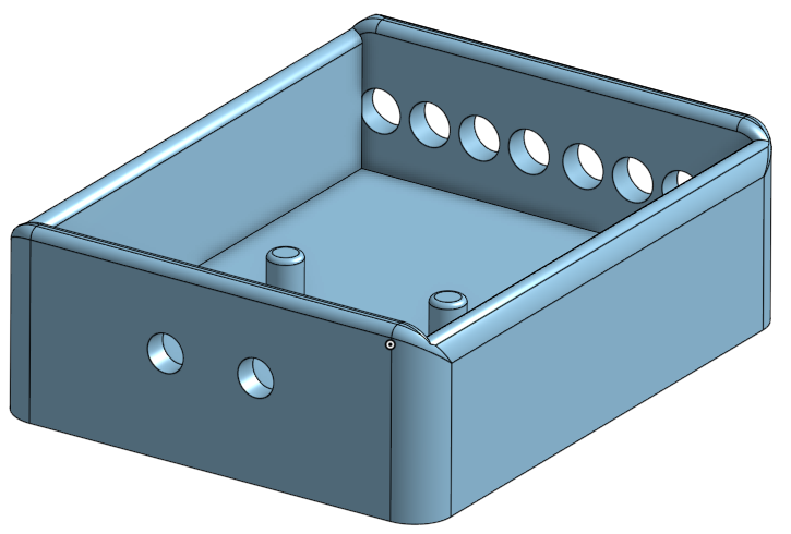
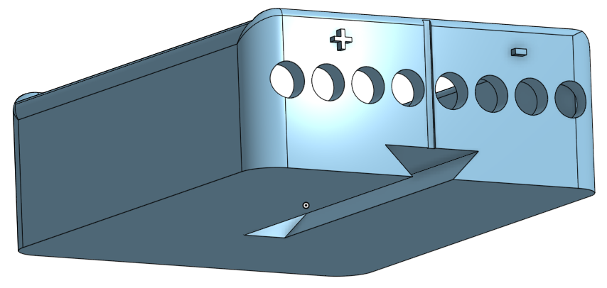
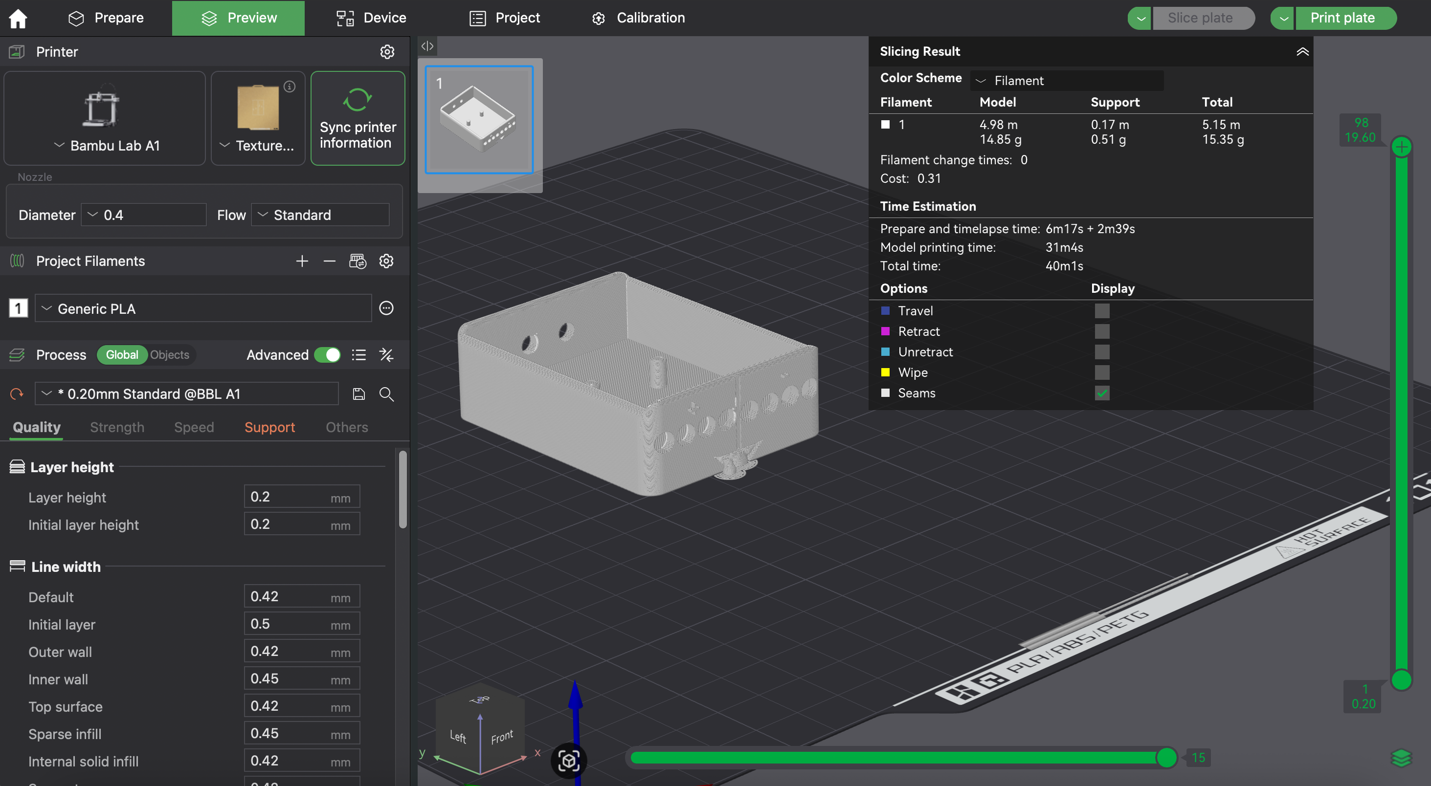
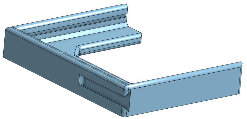
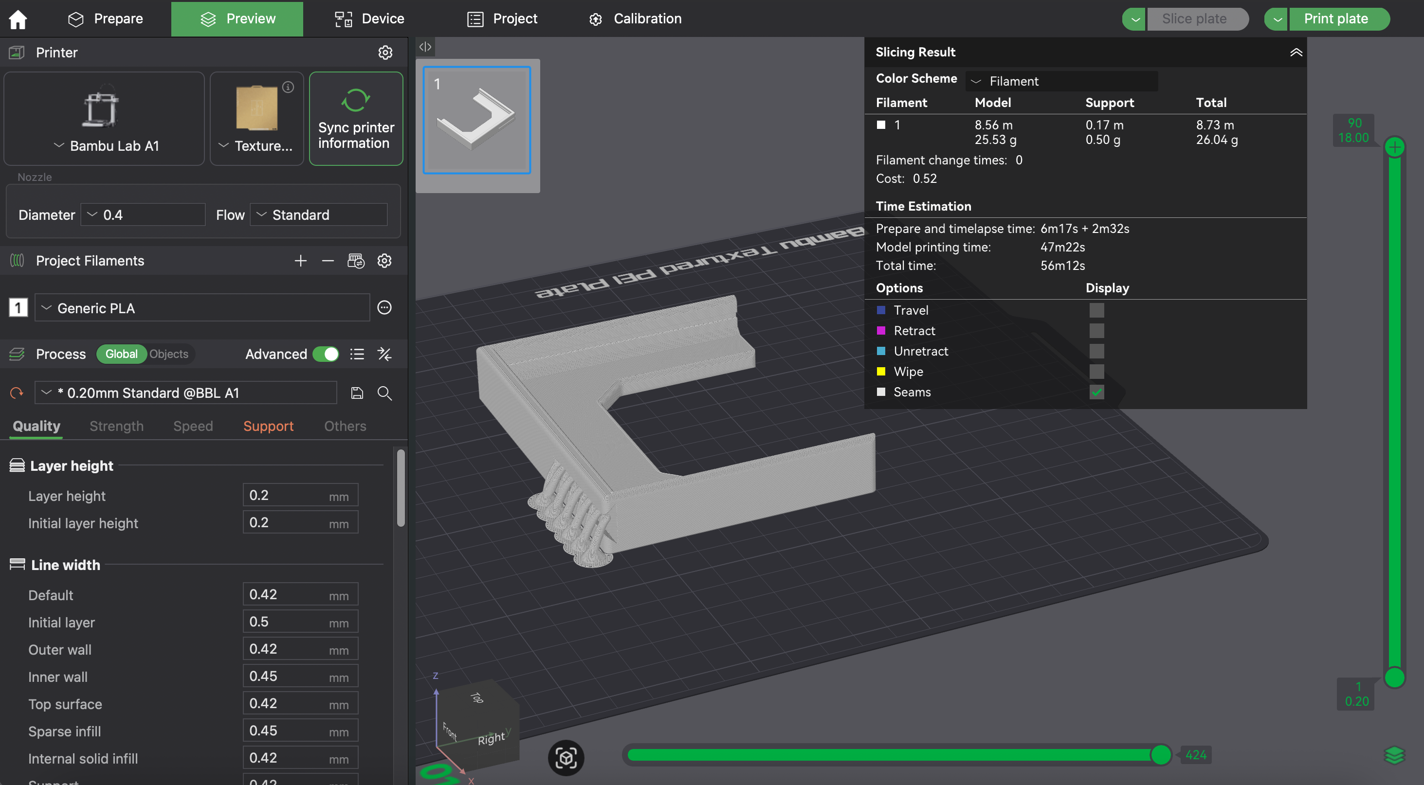
Jetson Support#
- Common Slicer Settings
- Supports: Yes
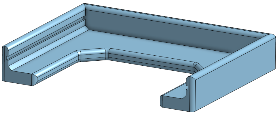
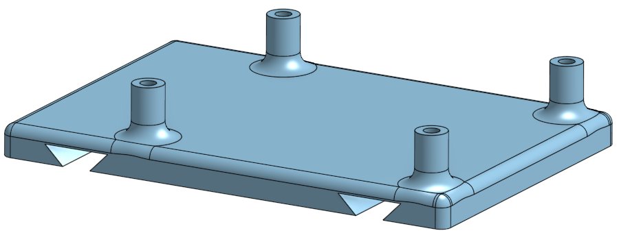
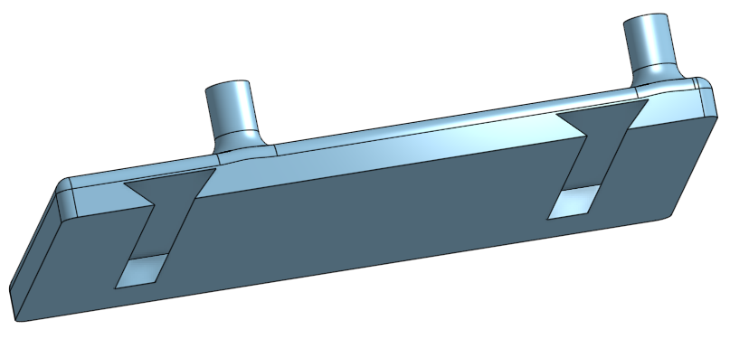
Microcontroller Support#
- Common Slicer Settings
- Supports: Yes
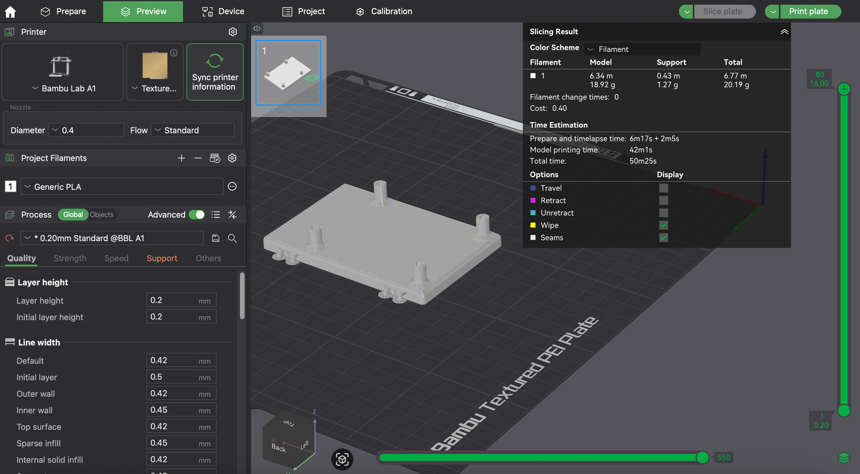
Router Support#
- Common Slicer Settings
- Supports: No
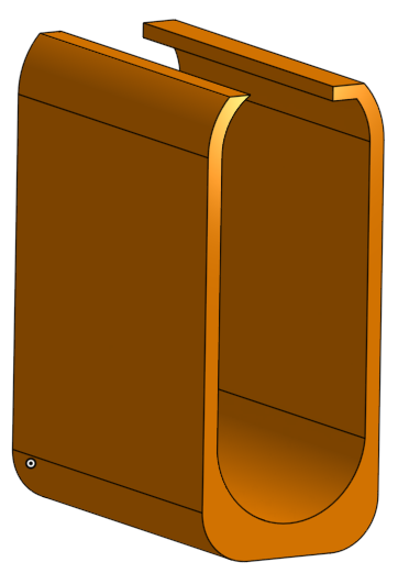
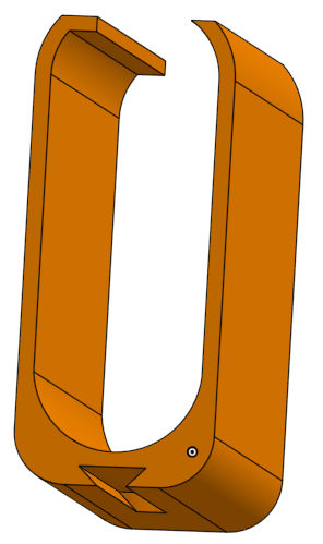
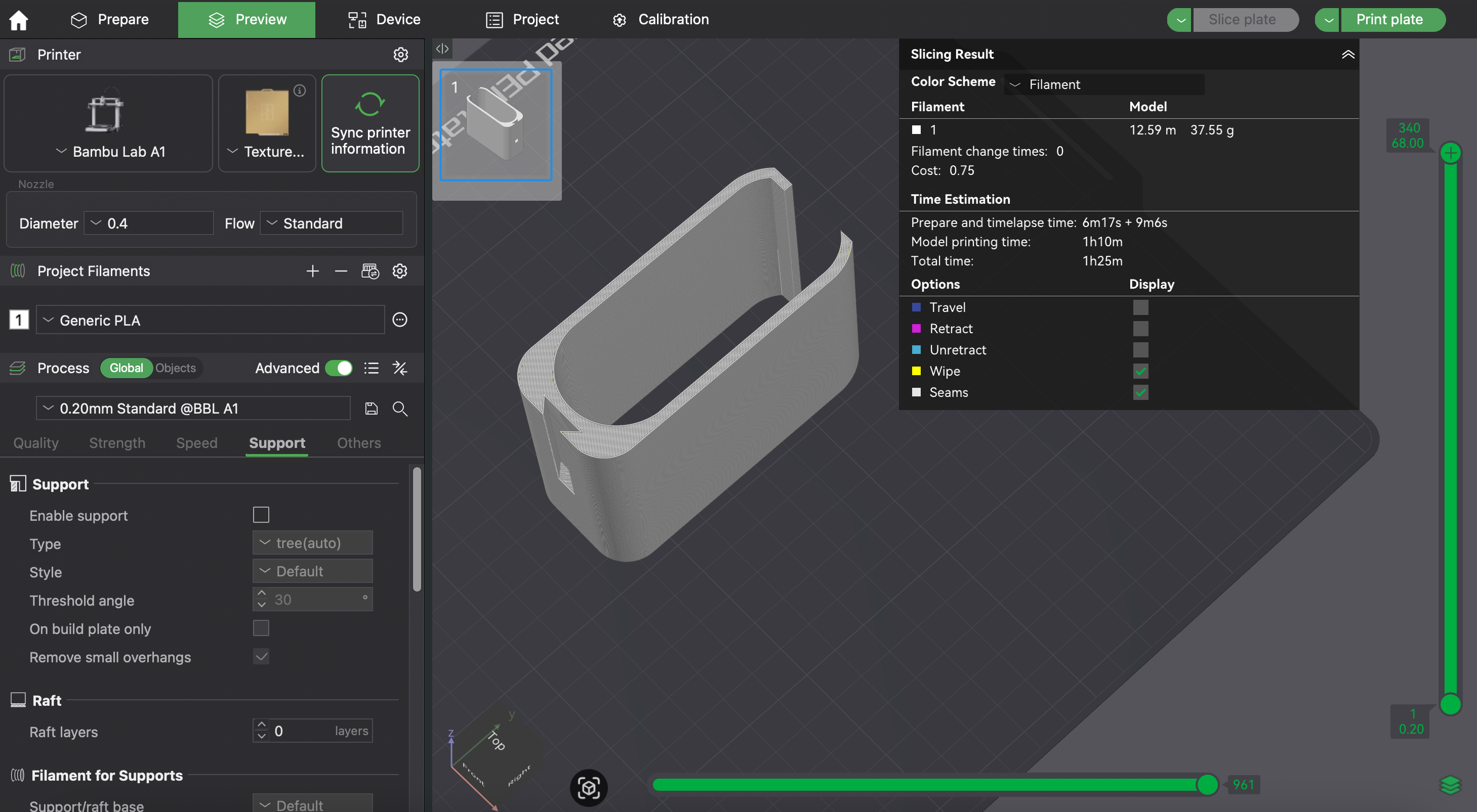
LiDAR Support#
- Common Slicer Settings
- Supports: Yes
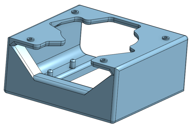
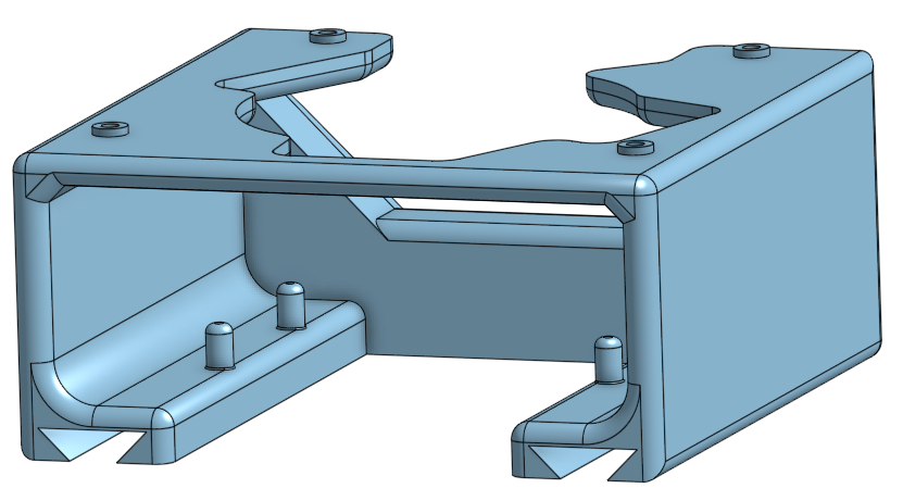
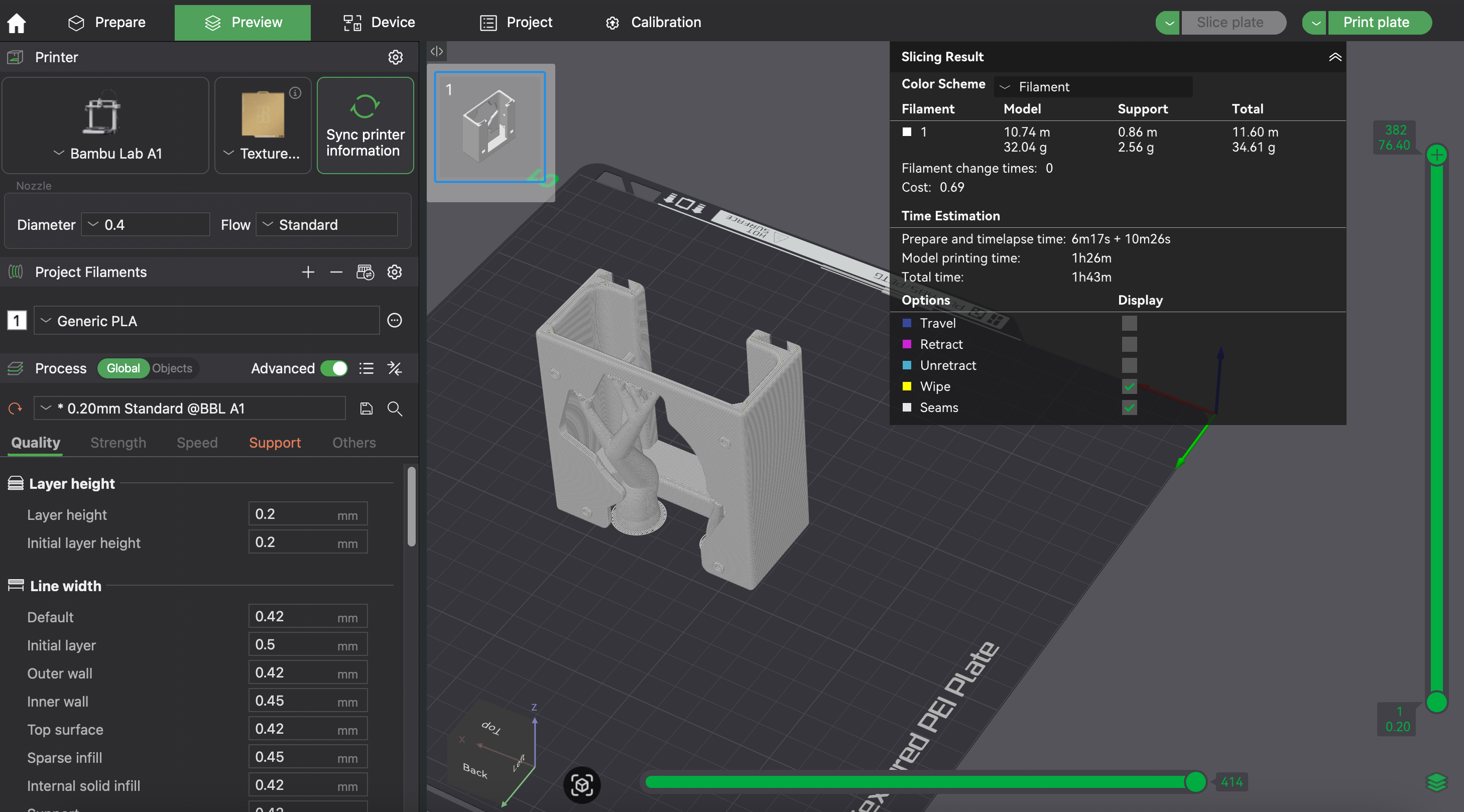
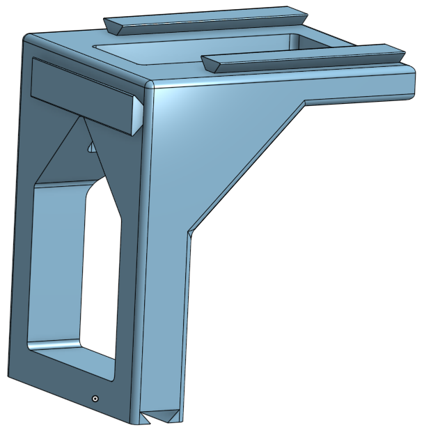
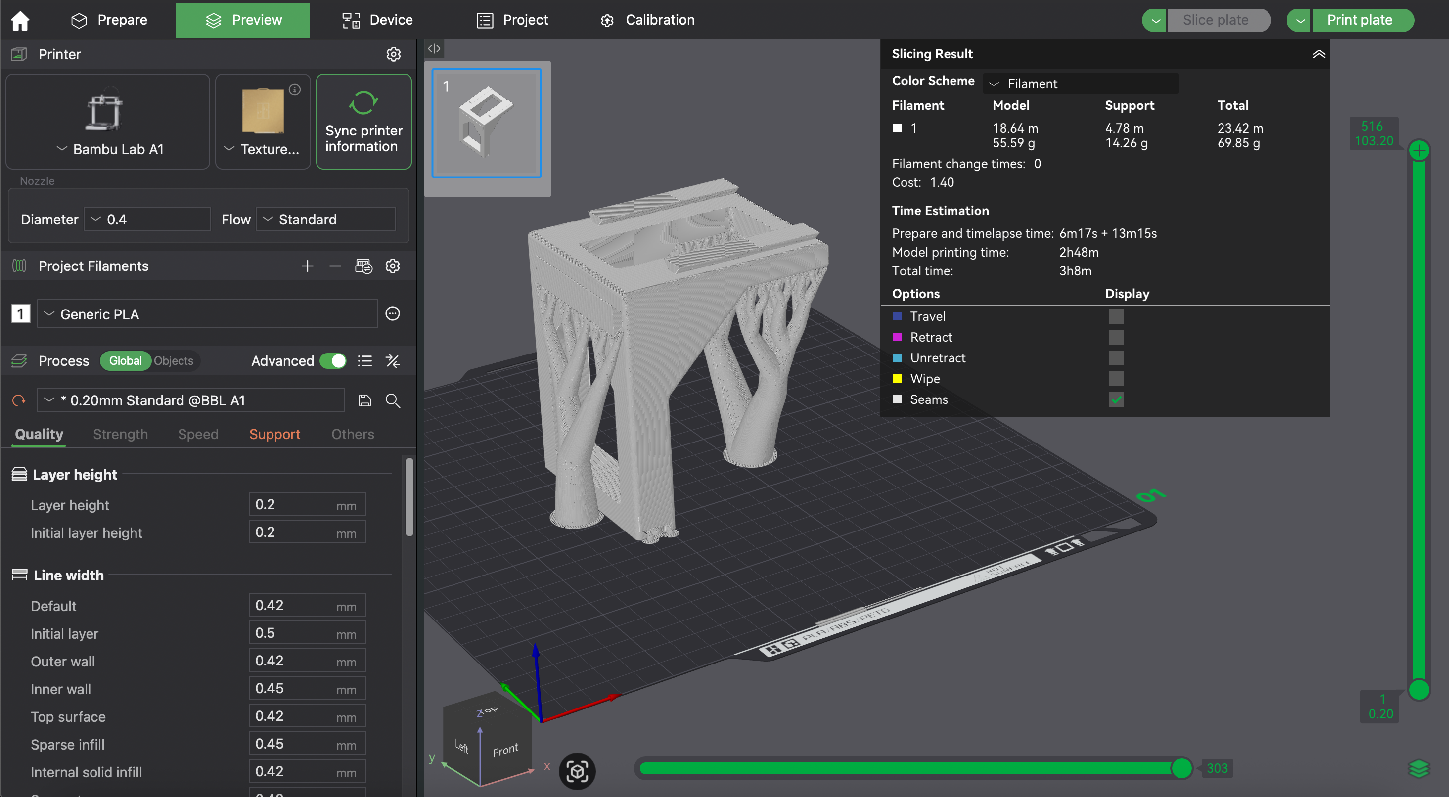
Extender#
- Common Slicer Settings
- Supports: Yes
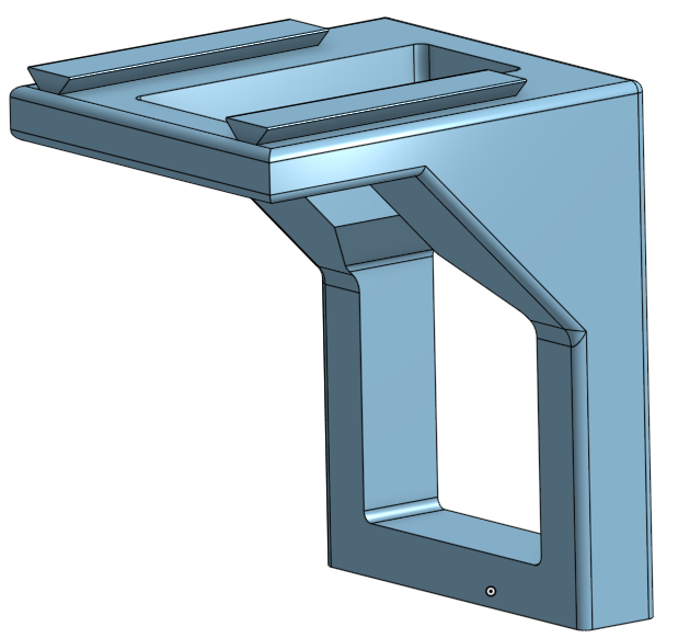
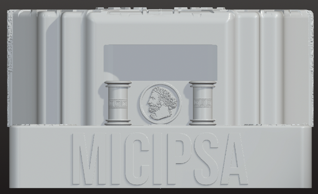
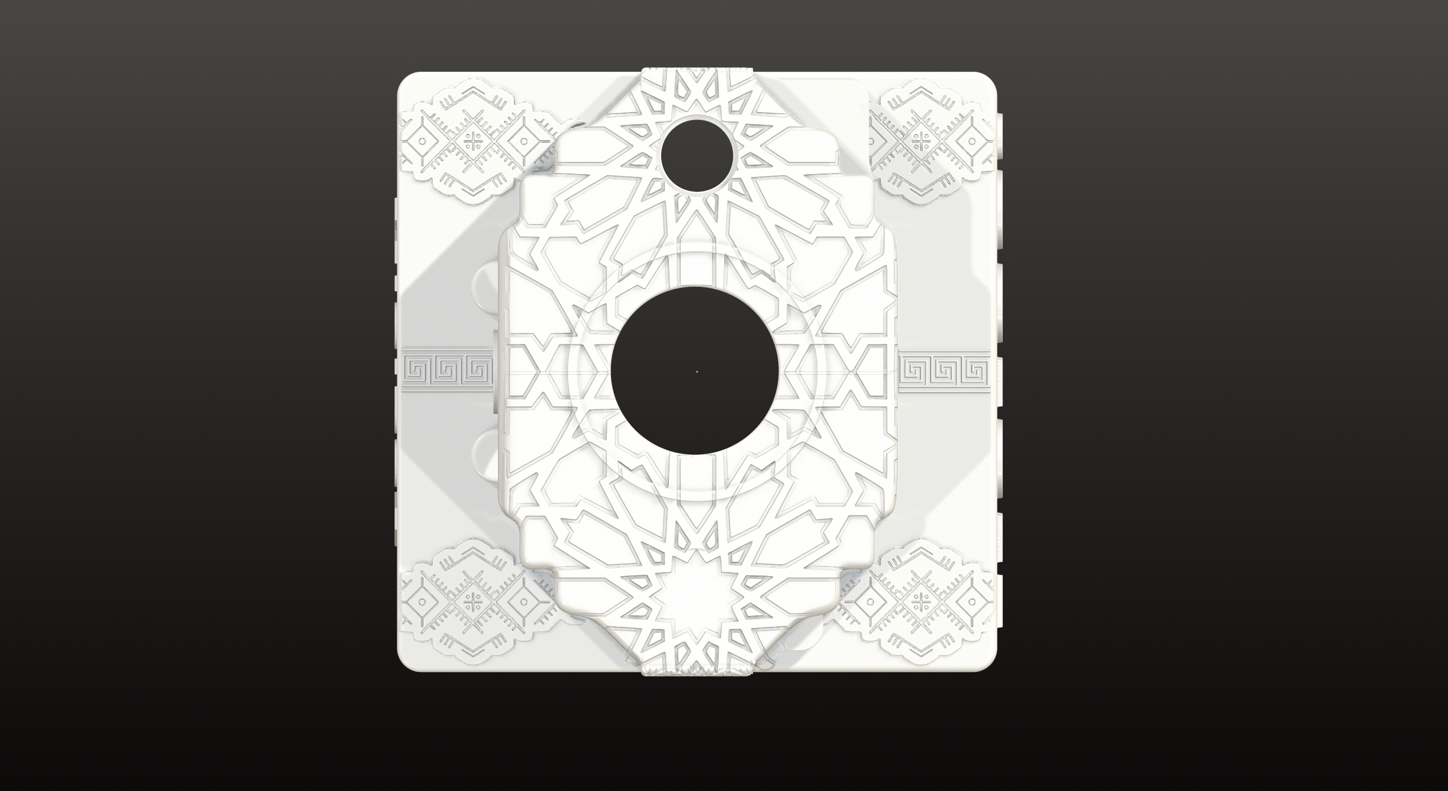
Shell#
- Common Slicer Settings
- Supports: Yes
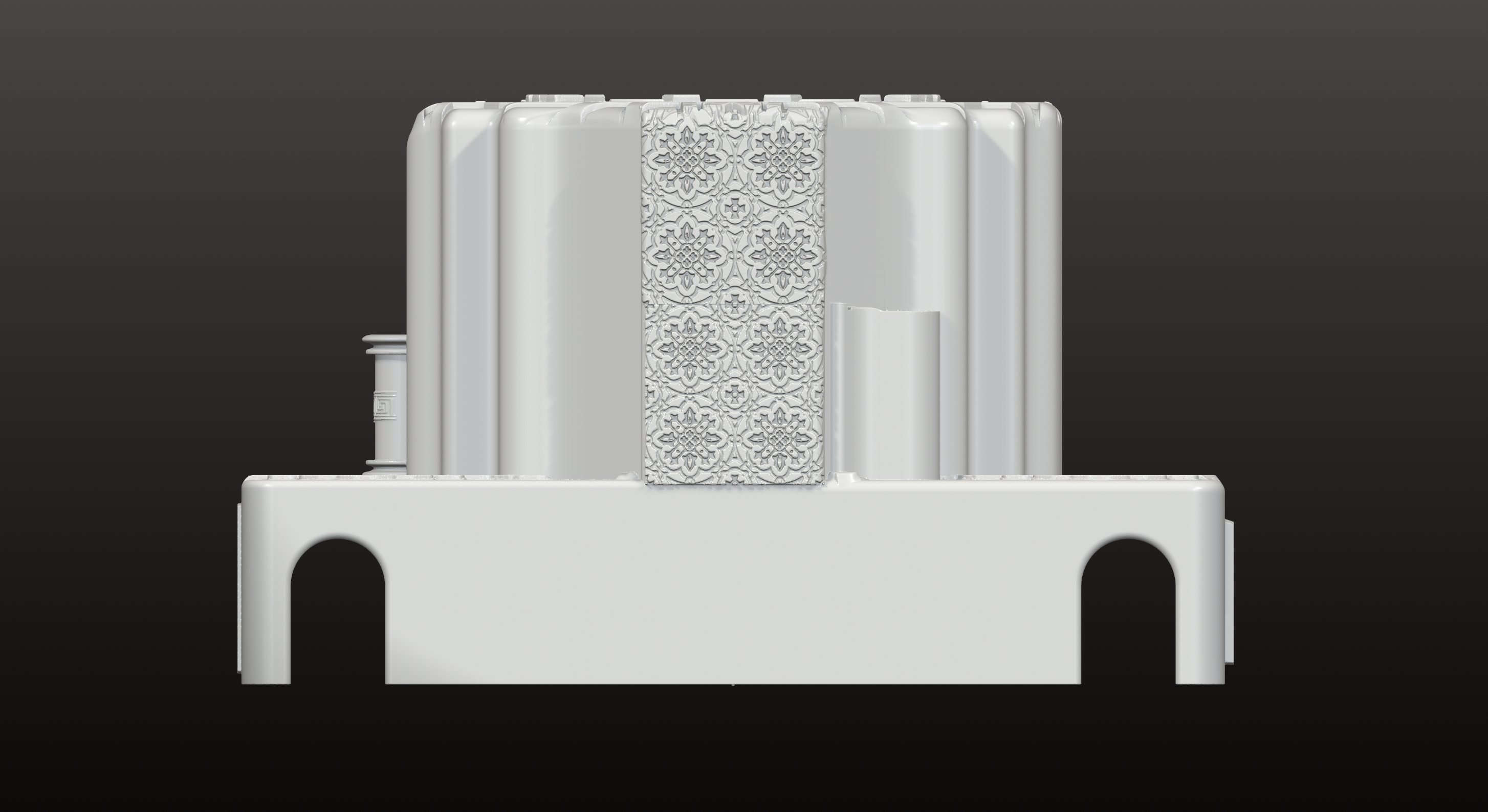
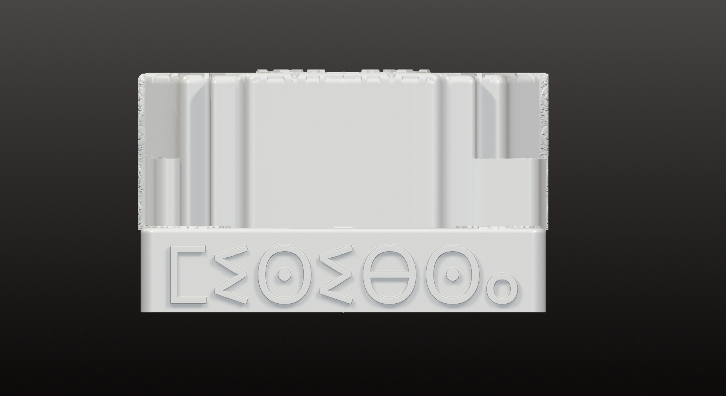
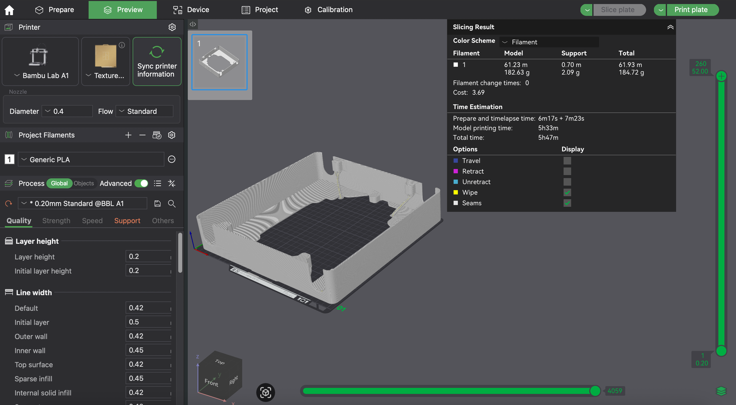
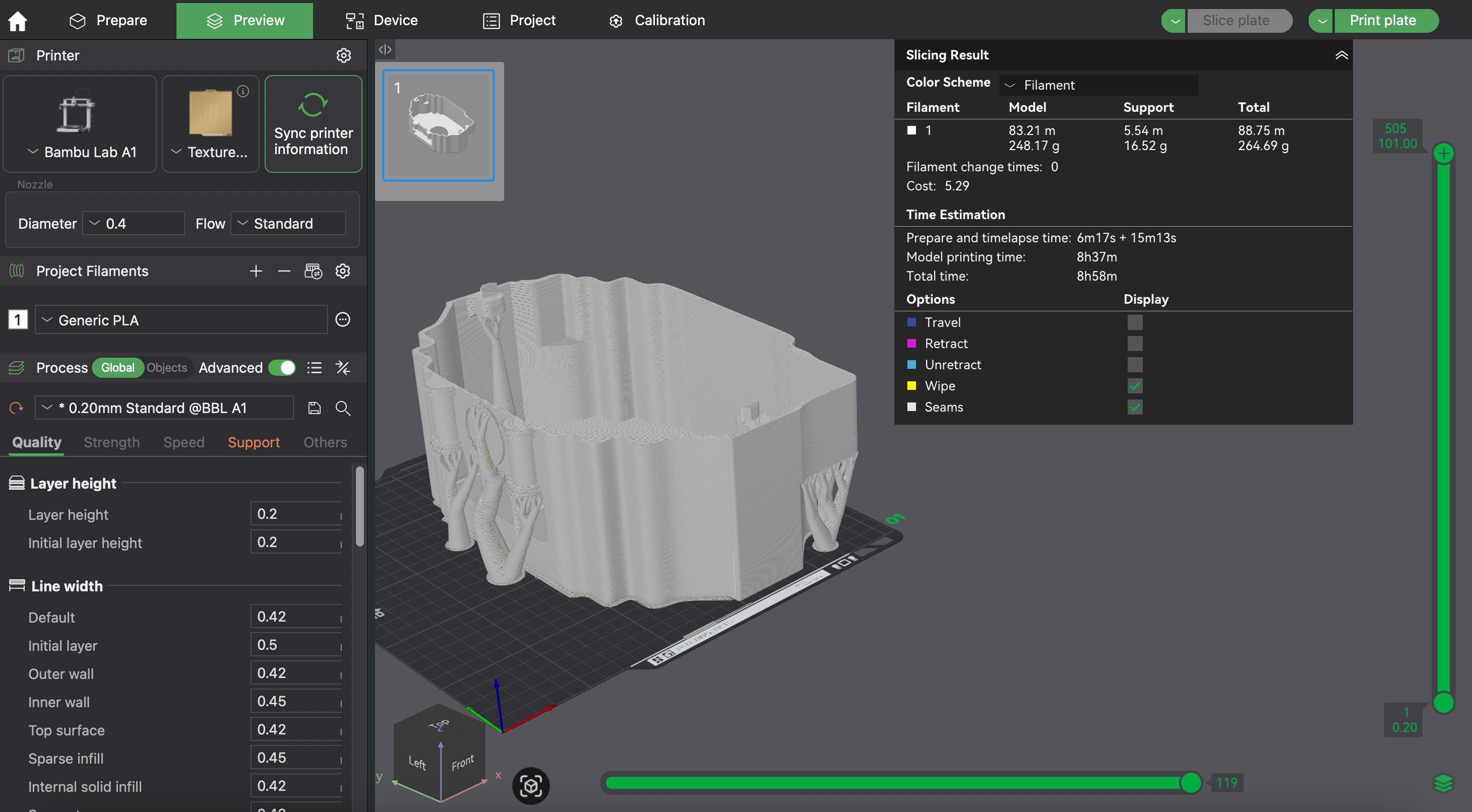
USB Hub Support#
- Common Slicer Settings
- Supports: No